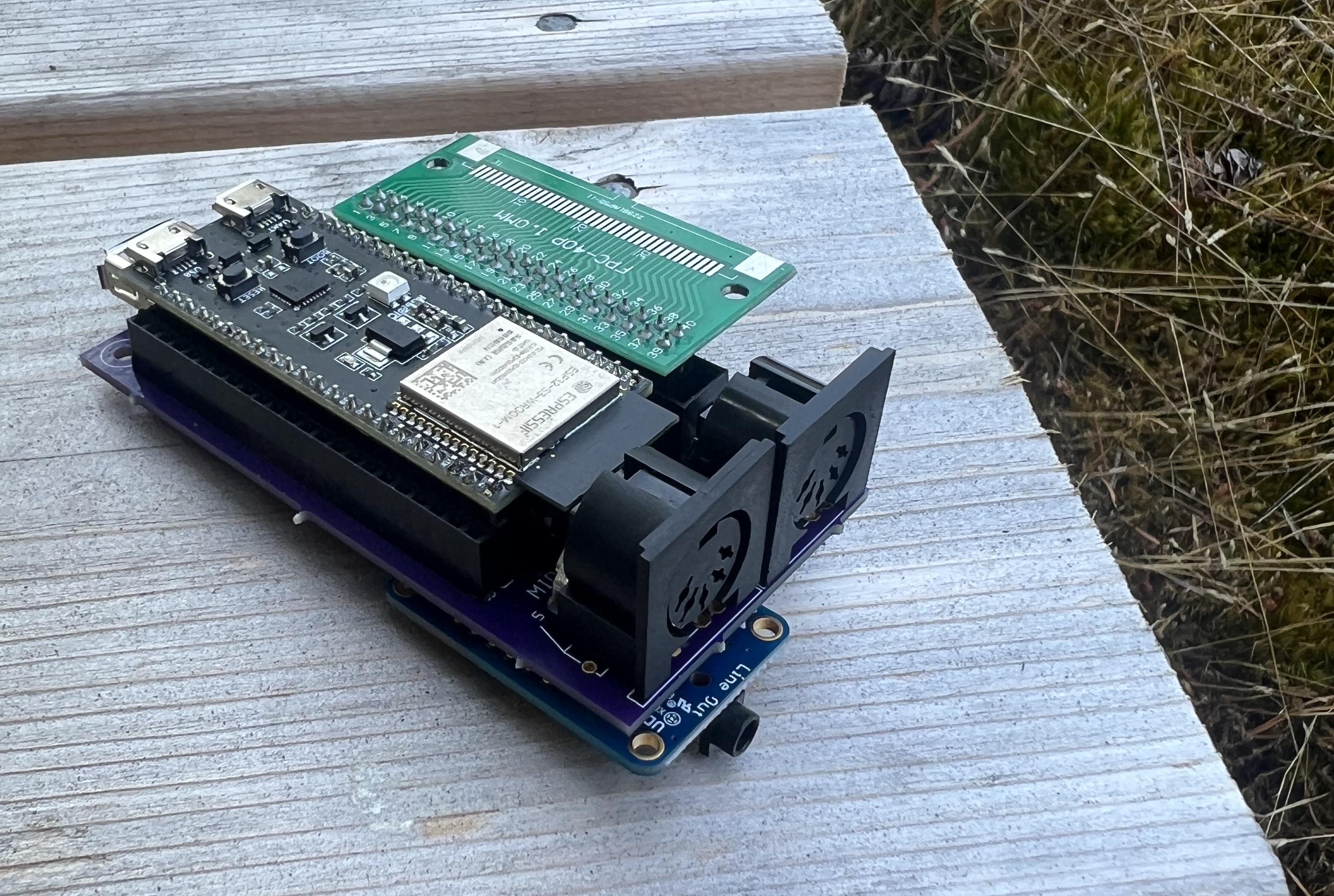
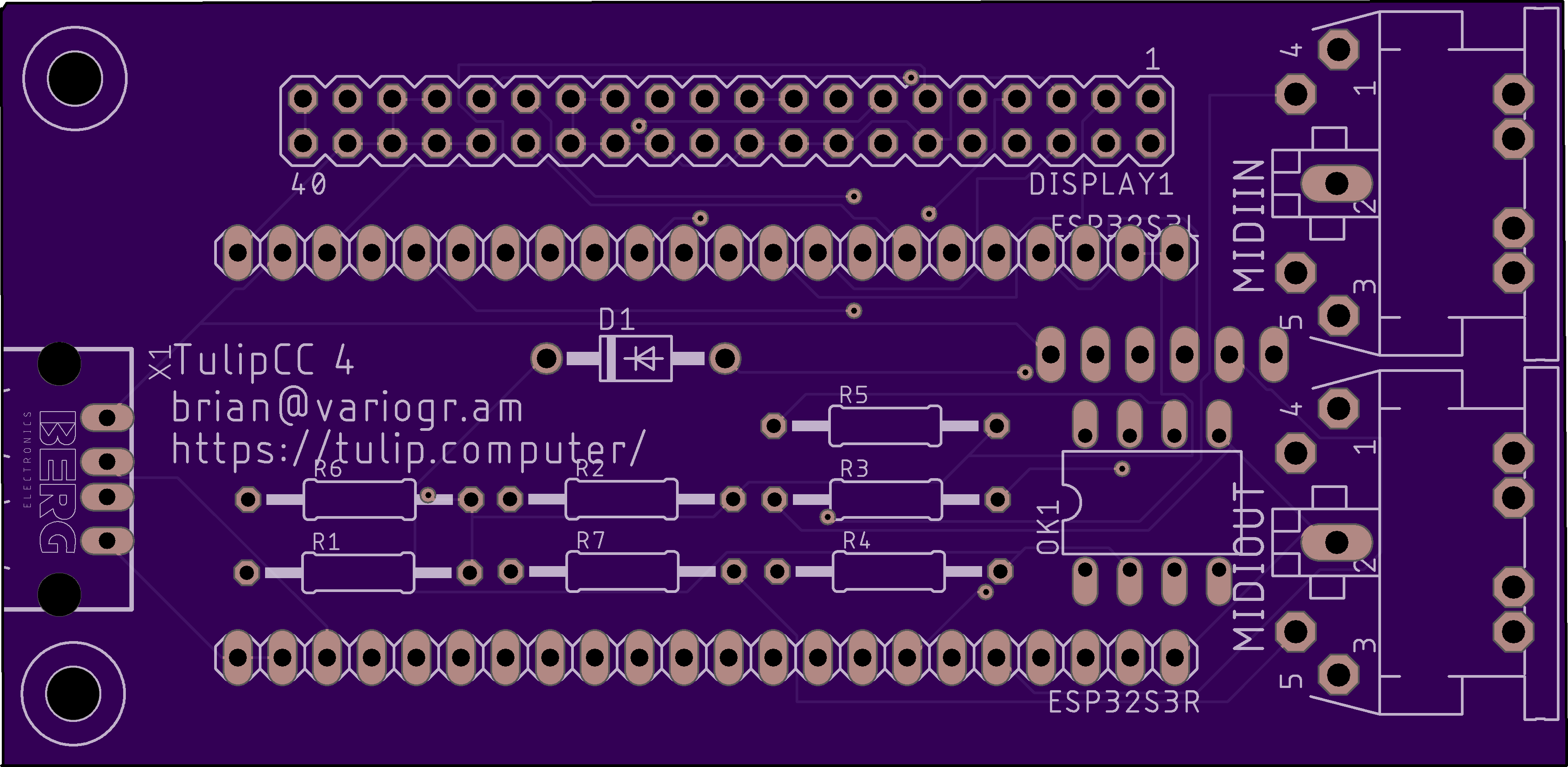
If you'd like a permament version of Tulip CC and can do through hole soldering, you can buy this breakout PCB I designed fron OSH Park.
If you'd rather make something more all-in-one, you can make a fully integrated surface mount board instead, or if you'd rather try something temporary or don't want to solder, build a Tulip on a breadboard.
Our breakout board PCB is $30 for 3 (this money goes all to OSH Park to manufacture the boards, I don't receive anything), and takes about a week to ship. The PCB is simply a way to connect the breakout boards without any jumper wires.
The Eagle files for this breakout PCB are here.
NOTE: the current version of the breakout board Tulip does not have support for the joystick port. We'll add it soon! If you really want that, build the breadboard or (r7+) integrated board version instead.
You'll need:
- ESP32-S3 WROOM-1 N32R8 dev board. The N32R8 has 32MB of flash. You can also use the N16R8 with 16MB of flash.
- This $58 RGB dot-clock 10.1" display with capacitive touch. Note other RGB dot clock displays of different sizes and resolutions can also work, but the pin numberings will be different and you'll have to update the resolution in our code.
- A 40-pin FPC header for the display.
- This stereo line-out / headphone jack UDA1334 DAC.
- Almost any USB keyboard should work.
- Connectors and random parts:
- Female headers are recommended, so you don't solder the ESP and audio jack directly to the PCB.
- I'd also get this 2x20 shrouded header for the display FPC breakout.
- 1 USB female A connector
- 2 female 5-pin DIN MIDI jacks
- 1 6N138 optoisolator and an 8-pin socket
- 7 resistors:
R1: 4.7K,R2: 4.7K,R3: 4.7K,R4: 220,R5: 470,R6: 33,R7: 10.R4throughR7don't have to be precisely those numbers, find the closest number that you have. - 1 diode: 1N4001
The assembly for our breakout PCB is simple. Solder the headers to the DISPLAY, ESP32S3L, ESP32S3R, and AUDIO rows. Solder the 8-pin socket where the 6N138 goes. Solder the resistors in their correct spots, and the diode (note the polarity.) Solder the USB connector. Solder the MIDI connectors. Then place the ESP32-S3 breakout in, the included FPC connector in (facing down, with the FPC cable going away from the board), the I2S board in, the 6N138 in, and connect a USB keyboard and the display to the FPC connector (to the displays' "RGB" input, the blue side facing up on both sides of the connector.) That's it!
After you're done assembling, read about how to compile and flash Tulip.
Any questions? Chat with us on our discussions page.

